Current Electricity Class 12 Notes: CBSE Digital Education provides the best revision notes for the chapter on current electricity class 12. Read the complete article and solve all-important questions related to current electricity class 12.
What is current electricity?
The study of electric charge in motion is known as current electricity.
What is the electric current?
The flow of electric charge through a conductor is called electric current.
- Electric current is a scalar quantity.
- Its SI unit is Ampere (A)
The electric current across an area held perpendicular to the direction of flow of charge is defined as the amount of charge flowing across that area per unit of time.

Electric current = charge/time
I = Q/T
The orders of magnitude of some electric currents we come across in daily life are:
Current in domestic appliances = 1 A
Electric Current carried by a lightening = 104 A
Current in our nerves = 10-6 A
Distinguish between conventional and electronic current
The direction of motion of the positive charge is taken as the direction of the conventional current. Electrons are negatively charged so the direction of the electronic current is opposite to that of the conventional current.
Maintenance of steady current in a circuit
The flow of electric current (or current) in a circuit is similar to the flow of water in a pipe. Suppose we wish to maintain steady water in a horizontal pipe from A to B.
Since the pressure at A is higher than that at B, so water flows spontaneously from the upper tank to the lower tank. To maintain a steady flow, a water pump must work at a steady rate to pump water back from the lower tank to the upper tank.
The water pump makes water flow from lower to higher pressure. It helps to preserve the pressure difference between A and B.
What is the electromotive force?
The EMF of a source may be defined as the work done by the source in taking a unit positive charge from its lower potential terminal to the higher potential terminal.
Electromotive force (or emf) is the energy supplied by the source in taking a unit positive charge once around the complete circuit. It is equal to the terminal potential difference measured in an open circuit.
EMF = work done/charge
= W/Q
If an electric chemical cell supplies the energy of 1 joule for the flow of 1-coulomb charge through the whole circuit then its emf is said to be 1 volt.
Difference between EMF and Potential difference
| Electromotive force (EMF) | Potential Difference |
| 2. Potential differences may exist between any two points or any two-point of a closed circuit. | 1. Work done by a source in taking a unit charge from one point of a circuit to another. |
| 2. It is equal to the maximum potential difference b/w the two terminals of a source when it is an open circuit. | 2. Potential differences may exist between any two points any two-point of a closed circuit. |
| 3. It exists even when the circuit is not closed. | 3. It exists only when the circuit is closed. |
| 4. it has a non-electrostatic origin. | 4. It has an electrostatic origin. |
| 5. It is larger than the p.d across any circuit element. | 5. It is always less than the emf. |
| 6. It is independent of the external resistance of the circuit. | 6. Potential difference is dependent on the external resistance of the circuit. |
| 7. It is a cause. | 7. It is an effect. |
State Ohm’s law
The electric current flowing through a conductor is directly proportional to the potential difference applied to its ends, provided the temperature and other physical conditions remain constant (or unchanged),
V ∝ I
V = IR
Where R is constantly called Resistance.
The proportionality constant R is known as the resistance of the conductor. Its value is independent of V and I but depends on the nature of the conductor, its length and area of cross-section, and physical conditions like temperature, etc. Ohm’s law may also be expressed as
R = V/I
The graph between the potential different V applied across a conductor to the current (I) flowing through it is a straight line.
Define resistance
Resistance is the property by virtue of which a conductor opposes the flow of electric charges through it.
Resistance is equal to the ratio of the potential difference (P.D) applied across the conductor to the current.
R = V/I
The SI unit of resistance is Ohm.
Any material that has some resistance is known as a resistor.
The resistance of a conductor is 1 Ohm if a current of 1A flows through it on applying a potential difference of 1 volt across its ends.
Factor affecting the resistance
At constant temperature, the resistance of the conductor depends on the following factors:
- The resistance is directly proportional to the length of the conductor (R L).
- The resistance of a uniform conductor is inversely proportional to its area of cross-section of the material (R 1/A).
- The nature of the material is also affected by resistance.
Then, R ∝ L/A
R = P L/A
Where Ρ is the constant of proportionality known as resistivity or specific resistance.
The resistivity of a material may be defined as the resistance of a conductor of that material having a unit length and unit cross-section area.
Resistivity is the resistance offered by the unit cube of the material of a conductor.
P = RA/L
The SI unit of resistivity is Ohm-metre.
What is the current density?
The amount of charge flowing per second through per unit area held normal to the direction of the flow of charge at that point.
Current density (j) is a vector quantity having the same direction as that of the motion of the positive charge. Its S.I. unit is Am-2.
J = q/tA = I/A
If area A is not perpendicular to the direction of current and normal to this area makes angle) with the direction of the current, then the component of A normal to the direction of current flow will be
An = A cosθ
Current density, j = I/An = I/Acosθ
Define the conductance of a material
The conductance of a conductor is the ease with which electric charge flows through it. It is equal to the reciprocal of its resistance and G denotes it.
Conductance, G = 1/Resistance
And its SI unit is (ohm)-1 or mho or Siemens.
Define the conductivity of a material
The reciprocal of the resistivity of a material is known as its conductivity.
- Conductivity = 1/Resistivity
- Its S.I. unit is Ohm-1m-1 or mho m-1 Sm-1
Classification of materials in terms of Resistivity
Conductors
The conductors conduct electric current fairly well. Metals are good conductors. They have low resistivity in the range of 10-8 m to 10-6 m.
Copper and aluminum have the lowest resistivity of all the metals, so their wires are used for transporting electric current over large distances without the applicable loss of energy.
On the other hand, nichrome wire has a resistivity of about 60 times that of copper (Cu). Nichrome is used in the elements of electric heater and electric iron.
Insulators
The conductors do not conduct electric current fairly well. Non-metals are good insulators. They have high resistivities of more than 104 m. Glass, Bakelite, and hard rubber have very high resistivities in the range of 1014 m. So insulators are used for blocking electric current between two points.
Semiconductors
Semiconductors are materials whose resistivities lie in between those of conductors and insulators that are between 10-6 m to 104 m. Germanium and silicon are typical semiconductors.
What are wire-bound and carbon resistors? Give the advantage of using carbon resistors.
Wire-bound and Carbon Resistors
Wire-bound resistors: These are made by winding the wires of an alloy on an insulating base. These alloys are relatively insensitive to temperature. But an inconveniently large length is required to make a high resistance.
Carbon resistors: Carbon resistors are made from a mixture of carbon molded into cylindrical rods by heating. These rods are enclosed in a ceramic or plastic jacket.
Advantages of using carbon resistors:
- Carbon resistors can be made with resistance values ranging from a few Ohms to several million ohms.
- They are quite cheap and compact.
- They are good enough for many purposes.
Carbon code for Carbon Resistors
It is used to indicate the resistance value of a carbon resistor and its percentage accuracy.
Carriers of current
The different types of current carriers are the following:
In Solid – In metallic conductors, electrons are the charge carriers. The electric current is due to the drift of the electrons from low to high potential regions. In n-type semiconductors, electrons are the majority charge carriers while in p-type semiconductors, holes are the majority charge carriers. A hole is a vacant state from which an electron has been removed and it acts as a positive charge carrier.
In liquids – In electrolytic liquids, the charge carriers are positively (+ve) and negatively (-ve) charged ions. For example, the CuSO4 solution has Cu2+ and SO42- ions, which act as charge carriers.
In gases – In ionized gases, positive (+ve) and negative (-ve) ions, and electrons are the charge carriers.
In vacuum tubes – In vacuum tubes like radio valves, cathode ray oscilloscopes, picture tubes, etc.; free electrons emitted by the heated cathode act as charge carriers.
Explain the drift velocity and relaxation time
In the absence of any electric field, the free electrons of metal are in a state of continuous random motion. At room temperature, their random velocities correspond to 105 m/s.
The average random velocity of free electrons is zero,
μ = (μ1+μ2+……+μn)/N = 0
Hence, there is no net flow of charges in any direction. In the presence of an external field, each electron experiences a force in the opposite direction of the external field and undergoes an acceleration (a),
Acceleration = Force/mass = –eE/m
As the electrons accelerate, they frequently collide with the positive metal ions or other electrons of the metals. Between two successive collisions, an electron gains a velocity component in the direction opposite to E.
The average time between two successive collisions is known as relaxation time.
T = (t1+t2+t3+……+tn)/N
During the relaxation time T, an electron gains an average velocity,
V = – (e E T)/m
It is called drift velocity.
Drift velocity: Drift velocity is defined as the average velocity gained by the free electrons of a conductor in the opposite direction of the externally applied electric field.
The relation between electric current and drift velocity
Let the potential difference (V) is applied across a conductor of length (l) and of uniform cross-section A. The electric field (E) set up inside the conductor is given by
E = V/l
Under the influence of field E, the free electrons begin to drift in the opposite direction of the electric field with an average drift velocity (Vd)
Let the number of electrons per unit or electron density = n
Charge on an electron = e
Number of electrons in length l of the conductor = nAl
Total charge contained in length l of the conductor = e nAl = q
Time is taken,
T = l/Vd
Current, I = q/t = enAl/l/Vd = enAVd
Deduction of Ohm’s law
If m is the mass of an electron and T is the relaxation time then drift velocity
Vd = eET/m
E = V/l
Vd = eVT/ml
Current I = enA x Vd
I = enA x evT/ml
I/V = ml/ne2TA
At a fixed temperature, the quantities m, l, n, e, T, and A, all have a constant value for a given conductor.
V/I = constant = R
Where R = m/ne2T x l/A
Resistivity in terms of electron density and relaxation time
The resistance R of a conductor of length l, area of cross-section A and resistivity p is given by
R =p x l/A
But R = ml/ne2TA
On comparing,
p = m/ne2T
p is independent of the dimensions of the conductors but depends on its two parameters.
Cause of resistance
Collisions are the basic cause of resistance (R). When a potential difference (V) is applied across a conductor, its free electrons get accelerated.
On the way, they frequently collide with the positive metal ions i.e., their motion is opposed and this opposition to the flow of electrons is known as resistance.
The larger the number of collisions per second smaller is the relaxation time T and the larger the will be resistivity.
P = m/ne2T
The number of collisions that the electrons make with the atoms/ ions depends on the nature of the materials (silver, copper, etc.) of the conductor
The resistance of a conductor depends on its length (l). A long wire offers more resistance than a short wire because there will be more collisions in the longer wire.
The resistance of the conductor depends on its area of cross-section. A thick wire offers less resistance than a thin wire because a thick wire has more area of cross-section available for the flow of electrons.
Why do alloys of metals have greater resistivity than their constituent metals?
In an alloy, ions occupy random locations relative to each other. An electron, therefore, passes through a very random medium and is very frequently deflected, so there are a small relaxation time and hence large resistivity.
Define the mobility of a conductor
The mobility of a charge carrier is the drift velocity (Vd) acquired by it in a unit electric field. It is given by
μ= Vd/E
Drift velocity Vd = qET/m
Then μ= qET/mE = qT/m
Discuss the effect of temperature on resistivity
- Metallic conductor
In metals, the total number of free electrons is fixed. As the temperature increases, the amplitude of the vibration of the atom increases. The collisions of electrons with these atoms become more frequent. The relaxation time T decreases, hence the resistivity increases.
- Semiconductor
In semiconductors, the relaxation time T does not change with temperature but the number density of free electrons increases exponentially with the increase in temperature. Hence the conductivity increases but resistivity decreases.
- Ionic conductor
The ionic conductor has both positive and negative ions as the charge carriers. As the temperature increases the electrostatic attraction between cations and anions decreases. Ions are freer to move and so the conductivity increase and resistivity decrease.
- Electrolyte
As the temperature increases, inter-ionic attraction decreases, and also viscous forces decrease, the ions move more freely. Hence conductivity increases and resistivity increases and resistivity decrease.
Why alloys are used for making standard resistors?
Alloys like constantan or manganin are used for making standard resistance coils because of the following reasons:
- They have a very small temperature coefficient so their resistance does not change appreciably even for several degrees rise of temperature.
- Alloys are least affected by atmospheric conditions like air moisture, etc.
- They have a high value of resistivity.
- Their contact potential with copper (Cu) is small.
Superconductivity
The phenomenon of complete loss of resistivity by certain metals and alloys, when they are cooled below a certain temperature, is known as superconductivity.
The temperature at which a substance undergoes a transition from a normal conductor to a superconductor in a zero magnetic field is known as transition or critical temperature.
A current once set up in a superconductor persists for a very long time without any apparent change in its magnitude.
Cause of superconductivity
It is believed that near the transition temperature, a weak attractive force acts on the electrons which brings them closer to form coupled pairs. Such coupled pairs are not deflected by ionic vibrations and so move without collisions.
Meissner effect
The expulsion of the magnetic flux from a superconducting material when it is cooled at a temperature below the critical temperature in a magnetic field is called the Meissner effect.
Application of superconductors
- It is used for the storage of memory in high-speed computers.
- It is used for producing high magnetic fields required for research work in high-energy physics.
- It is used in the construction of very sensitive galvanometers.
- It is used for long-distance power transmission without any wastage of power.
- It is used in levitation transportation (trains that move without rails).
What is meant by equivalent resistance of a combination of resistance?
If a combination of two or more resistance in an electric circuit can be replaced by a single resistance such that there is no change in the current in the circuit and in the potential difference between the terminals of the combination, then the single resistance is called the equivalent resistance of the combination.
Types of the combination of resistances
- Series combination of resistance
- The parallel combination of resistances
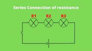
Series combination of resistances
Suppose a number of resistances are connected end to end so that the same current flows through each one of them in succession.
Suppose 3 resistances (R1, R2, and R3) are connected in series. Let V be the potential difference is applied across the combination, the same current I is flowing through each resistance.
By Ohm’s law, the potential difference V drops across the three resistances are
V1 = (I x R1), V2 = (I x R2), V3 = (I x R3)
If Rs is the equivalent of the series combination,
V = IRs
V = V1 + V2 + V3
IRs = IR1 + IR2 + IR3
Rs = R1 + R2 + R3
Laws of Resistance in series
- Electric current (I) through each resistance is the same.
- The total potential drop is equal to the sum of potential drops across the individual resistances.
- Individual potential V drops are directly proportional to individual resistances.
- Equivalent resistance Rs = Sum of the individual resistances.
- The equivalent resistance is larger than the largest individual resistances.
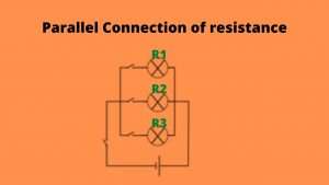
The parallel combination of resistances
In a number of resistances are connected in between two common points so that each of them provides a separate path for current (I).
Three resistances R1, R2, and R3 are connected in parallel combinations. Suppose V be the potential difference applied across the combination. Let I1, I2, ad I3 be the currents through the resistances R1, R2, and R3 respectively.
Then the current in the main circuit must be I = I1 + I2 + I3
By Ohm’s law, the currents through the individual resistances will be
I1 = V/R1 , I2 = V/R2 , I3 = V/R3
If Rp is the equivalent resistance of the parallel combination, then we must have
I = V/RP
V/RP = V/R1 + V/R2 +V/R3
1/RP = 1/R1 + 1/R2 + 1/R3
Laws of Resistance in Parallel
- The potential difference V across each resistance is the same.
- Total current (I) is equal to the sum of the currents through individual resistances.
- Individual currents (I) are inversely proportional to individual resistances.
- The reciprocal of equivalent resistance (R) is equal to the sum of the reciprocal of individual resistances.
- The equivalent resistance is less than the smallest individual resistances.
Combination of Resistances

What is the internal resistance of the cell?
The resistance followed by the electrolyte of a cell to the flow of current between its electrodes is known as the internal resistance of the cell.
The internal resistance of the cell depends on the following factors:
- It is directly proportional to the concentration of the electrolyte.
- It is directly proportional to the distance between the two electrodes.
- Nature of electrolytes.
- It varies inversely as the common area of the electrodes immersed in the electrolyte.
- It increases with the decrease in the temperature of the electrolyte.
Define the terminal potential difference of a cell
The potential drop across the terminals of a cell, when a current is being drawn from it, is called its terminal potential difference (V).
- When the cell is an open circuit then I = 0.
- The potential difference across the terminal of the cell in a closed circuit is always less than its emf.
What do you mean by the heating effect of current?
Heating effect of electric current
The phenomenon of the production of heat in a resistor by the flow of an electric current (I) through it is called the heating effect of current or Joule heating.
Cause of heating effect of current
When a potential difference is applied across the ends of a conductor its free electrons get accelerated in the opposite direction of the applied field. But the speed of the electrons does not increase beyond a constant drift speed. This is because, during the cause of their motion, the electrons collide frequently with the positive (+ve) metal ions.
The kinetic energy gained by the electrons during the interval of free acceleration between collisions is transferred to the metal ions at the time of the collision.
The metal ions begin to vibrate about their mean positions more and more violently. The average K.E. of the ions increases. This increases the temperature of the conductor. Thus the conductor gets heated due to the flow of current.
Heat produced in resistance is:
- Directly proportional to the resistance (R) for a given I.
- Directly proportional to the I2 for a given R.
- Inversely proportional to the resistance R for given V.
- Directly proportional to the time (t) for which the current (I) flows through the resistor.
H =VIt = I2Rt = V2t/R
Application of heating effect of current
Some of the important applications of Joule heating are as follows:
- Household electrical appliances
Many electrical appliances used in daily life are based on the heating effect of current (or Joule Heating) like electric iron, room heater, electric toaster, electric oven, electric kettles, etc.
The resistor should have high resistance so that most of the electric power is converted into heat.
In most household heating appliances (electric iron, electric heater, etc), nichrome element is used because of the following reasons:
- Its melting point is very high
- Its resistivity is large
- It can be easily drawn into wires (tensile property)
- It is not easily oxidized by the oxygen (O2) of the air when heated.
- Electric fuse
It is a safety device used to protect household electrical appliances from strong currents. An electric fuse wire must have high resistivity and a low melting point. It is usually made from an alloy of tin (63%) and lead (37%). It is connected in a series connection with the live wire of the circuit.
When the current (I) exceeds the safety limit, the fuse wire melts and breaks the circuit. The electric installations are thus saved from getting damaged of household appliances. The fuse wire of suitable electric current rating is 1A, 2A, 3A, 5A, 10A, etc.
- Incandescent electric bulb
It is an important application of the heating effect of current in producing light. It consists of a filament of fine metallic wire enclosed in a glass bulb filled with chemically inactive gases like nitrogen (N) and argon (Ar).
When current is passed through the bulb filament, it gets heated to a high temperature and emits light.
Most of the electric power consumed by the filament is converted into heat and only a small part of it appears as light. A bulb gives nearly 1 candela of light energy for the consumption of every watt of electric power.
- Electric Arc
It consists of two carbon rods with a small gap between their pointed ends. When a high potential difference of 40-60 V is applied between the two rods, very intense light is emitted by the gap.
When the electric field exceeds the dielectric strength of air, ionization of air occurs. This causes a big spark to pass across the gap.
Other devices
Many other devices are based on Joule heating such as electric welding, hotwire ammeters, thermionic valves, and voltmeters.
Define the term electric power and electric energy
Define electric power
Electric power is the rate at which an electrical appliance converts electric energy into other forms of energy or it is the rate at which work is done by a source of emf in maintaining an electric current through an electric circuit.
Electric power is denoted by P. Its SI unit is a watt.
P = Work/time = V x I = I2 x R = V2/R
1 Watt: The power of an appliance is one watt if 1 Ampere (A) of current flows through it on applying a potential difference of 1 volt across it.
Define electric energy
Electric energy is the total work done in maintaining an electric circuit for a given time.
W = P x t = V I t = I2Rt
SI unit of electric energy is Joule and the commercial unit of energy is Kilowatt-hour (KWh).
Relationship between KWh and Joule,
One KWh = 1 KW in 1 Hour
1 KWh = 1000 watts in 1 Hour
1 KWh = 1000 Joule/seconds X 60 X 60 seconds
1 KWh = 3600000 Joule
1 KWh = 3.6 x 10⁶ Joule
Kirchhoff’s Laws
In 1942, a German physicist Kirchhoff extended Ohm’s too-complicated circuits and gave two laws, which enable us to determine the current in any part of such a circuit.
Before understanding these laws, we first define a few important terms:
Electric Network: The term electric network is used for a complicated system of electrical conductors.
Junction: Any point in an electric circuit where two or more conductors are joined together is a junction.
Loop or Mesh: Any closed conducting path in an electric network is known as a loop or mesh.
Branch: A branch is any part of the network that lies between two junctions.
Kirchhoff’s first law
In an electric circuit, the algebraic sum of currents at any junction is zero. Or, the sum of currents entering a junction is equal to the sum of currents leaving that junction. The first law is also known as Kirchhoff’s current law (KCL).
This law may be expressed as = 0
Sign convention for applying junction rule
- The currents flowing towards the junction are taken as positive (+ve).
- The currents flowing away from the junction are taken as negative (-ve).
Suppose a junction J in a circuit where 4 currents meet. The currents I1 and I2 flowing towards the junction are positive while the currents I3 and I4 flowing away from the junction are negative, therefore, by the junction rule:
∑ I = 0
I1 + I2 – I3 – I4 = 0
Incoming current = Outgoing current
Kirchhoff’s second law
Around any closed loop of the network, the algebraic sum of changes in potential must be zero. Or, the algebraic sum of the emf in any loop of a circuit and resistance in it.
Sign convection for applying loop rule
- We can take any direction (clockwise or anti-clockwise) as the direction of traversal.
- The emf of the cell is taken as positive if the direction of traversal is from its negative to the positive terminal (through the electrolyte).
- The emf of a cell is taken as negative if the direction of traversal is from its positive to the negative terminal.
- The current-resistance (IR) product is taken as positive if the resistor is traversed in the same direction as the assumed current.
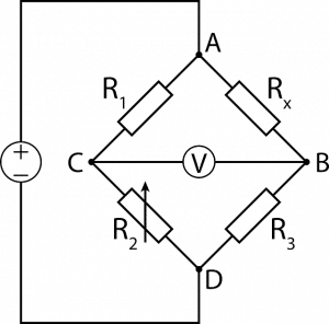
What is a Wheatstone bridge?
It is an arrangement of four resistance used to determine one of this resistance, quickly and accurately in terms of the remaining three resistances.
What is meant by the sensitivity of a Wheatstone bridge?
A Wheatstone bridge is said to be sensitive if it shows a large deflection in the galvanometer (G) for a small change of resistance (R) in the resistance arm.
It depends upon:
- Relative magnitudes of the resistance in the four arms of the bridge. The bridge is most sensitive when all four resistance is of the same order.
- The relative position of the battery and galvanometer.
According to Callender for the greater sensitivity of the Wheatstone bridge, the battery should be so connected that the resistance in series with the resistance to be measured is greater than the resistance in parallel with it.
According to Maxwell for the greater sensitivity of the Wheatstone bridge, out of the battery and the galvanometer, the one having the higher resistance should be connected between the junction of the 2 highest resistances and the junction of the 2 lowest resistances.
What is the advantage of a Wheatstone bridge method?
The bridge method has the following advantages of other methods for measuring resistance:
- It is the null method. Hence the internal resistance of the cell and resistance of the galvanometer does not affect the null point.
- As the method does not involve any measurement of current and potential difference, the resistances of ammeters and voltmeters do not affect the measurements.
We hope you like this article about Current electricity class 12 Notes. Comment below for any query related to the Current Electricity Class 12 Notes article.