Let’s start the complete discussion about the important topic “what is transistor”. If you read the complete article then you solve the all-important question of the transistor topic.
What is Transistor?
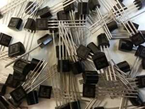
It is a semiconductor device used for amplifying or switching electronic signals and electric power. It is composed of semiconductor materials usually with at least three terminals for connection to an external circuit.
A voltage or current is applied to one pair of the terminals of the transistor which controls the current through another pair of terminals. Because the controlled (output) power can be higher than the controlling (input) power, a transistor can amplify a signal. These transistors are found embedded in integrated circuits.
- The transistor is used for rectification, amplification, oscillation, etc.
- Transistor: Transfer + Resistor
- The current is transferred from a low resistance to a high resistance circuit.
Their use has revolutionized the field of electronics and paved the way for smaller and cheaper radios, computers, and calculators, among other things.
Types of transistors
There are two types of transistors:
- Bipolar transistor
- Field-effect transistor
Bipolar Transistor
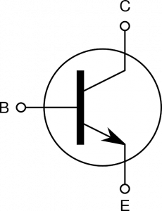
It has terminals labeled base, collector, and emitter. A small current at the base terminal (i.e., flowing between the base and the emitter) can control or switch a much larger current between the collector and emitter terminals.
Field-effect Transistor
Field-effect transistors are labeled as the gate, source, and drain, and a voltage at the gate can control a current between the source and drain. In transistors, the collector region is physically larger than the emitter region. For its biasing, the emitter-base junction is always forward-biased while the collector-based junction is always reverse-biased.
Legs of Transistor
There are 3 legs of transistor:
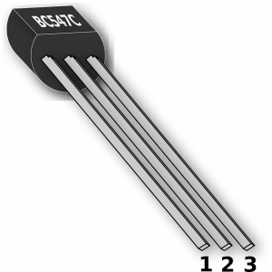
1. Emitter
Heavily doped crystal supplies/emits the majority of charge carriers.
Moderate Size: Thinner than the collector and thicker than the base.
2. Base
Lightly doped crystal and made very thin. It passes most of the emitter-injected charge carriers to the collectors.
Collector
Moderately doped crystal thickest in size. Collect/remove majority charge carriers coming from the emitter.
Photoconductivity
The increase in the conductivity of a semiconductor as a result of incident photons of suitable energy is called photoconductivity. Semiconductors having large productivity are used as light-dependent resistors (LDR) in automatic light control circuits.
p – n Junction
It is a crystal of Ge or Si-doped in such a manner that one-half portion of it acts as a p-type semiconductor and another half as an n-type semiconductor.
The term junction implies the boundary or region of transition between n-type and p-type semiconductor materials.
A p-type crystal sandwiching between two n-type crystals while an n-type crystal sandwiching between two p-type crystals.
Working of p-n-p Transistor
- The base is common with Emitter and Collector.
- The emitter-Base junction is given a small forward bias.
- Collector-Base junction is given a large reverse bias. Holes move from the emitter towards the base.
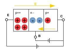
Most of them (nearly 98%) cross the base and enter into the collector region while very few (nearly 2%) combine with the electrons in the base an electron leaves the negative terminal of battery VE and enters into the base. This causes a small base current IB. the holes entering into the collector region combine with the electrons coming from the negative terminal of Vc. this causes collector current Ic.
The base current may be nearly 2 to 10% of the emitter current depending on the doping level. Similarly collector current may be nearly 90 to 98% of the emitter current.
The holes are the charge carriers within the transistor while electrons are charge carriers in the external circuit.
Working of n-p-n Transistor
- The base is common with Emitter and Collector.
- Emitter-Base junction is given small forward bias.
- Collector-Base junction is given large reverse bias.
Forwards bias in the emitter-base region, electrons from the emitter-region move towards the base. Most of them (nearly 98%) cross the base and enter into the collector region move while very few (nearly 2%) combine with the holes in the base.
This electron is captured by a positive terminal of the battery VE and sends it towards the emitter region. This causes a small base current IB. These electrons entering into the collector region are attracted by the positive terminal of Vc. This causes collector Ic.
These two currents combine to constitute emitter current iE. Thus, iE = iB + iC.
The base current may be 2 to 10% of the emitter current depending on the doping level. Similarly, the collector current may be 90 to 98% of the emitter current. The electrons are the charge carriers within the transistor as well as in the external circuit.
Transistor and Circuit
A transistor can be connected in a circuit in the following three configurations; Common Base (BC), Common Emitter (CE), and Common Collector (CC).
Transistor as a Switch
Transistors are commonly used in digital circuits as electronic switches which can be either in an “on” or “off” state in a grounded-emitter transistor circuit, such as the light-switch circuit shown, as the base voltage rises, the emitter and collector currents rise exponentially. The collector voltage drops because of reduced resistance from the collector to the emitter.
When the voltage difference between the collector and emitter was zero (or near zero), the collector current would be limited only by the lead resisted (light bulb) and the supply voltage. This is called saturation because the current is flowing from the collector to the emitter freely. When the transistor is saturated, the switch is said to be on, and when not, it is considered switched off.
Transistors as an amplifier
The common-emitter amplifier is designed so that a small change in the voltage (Vin) may change the small current through the base of the transistor; the current amplification of the transistor combined with the properties of the circuit means that small swings in Vm produce large changes in Vout.
From mobile phones to televisions, vast numbers of products include amplifiers for sound reproduction, signal processing, and radio transmission. Modern transistor audio amplifiers of up to a few hundred watts are common and relatively inexpensive.
We hope you like this post “What is transistor?”. Comment below for other important topics.
I am 12 th class student and your article is very helpful for class 12th student.
Please provide total class 12 cjapter notes
Reply sir
thanks
ok I provided all chapter
I am often to blogging and i really appreciate your content. The article has really peaks my interest. I am going to bookmark your site and keep checking for new information.